
Remote ID Broadcast Module Assembly Instructions
Ready to assemble your module and get flying? Lets get to it!
The video below has a demonstration of us soldering the whole module together. It takes us between 10-15 minutes to complete the whole assembly. Detailed step-by-step instructions are below the video.
Please reach out to team@cinnamondrones.com if you need assistance.
Step-by-step instructions
Time: About 15-20 minutes assembly time
Materials: All materials should be in the package
GPS module
GPS wires (with JST connector)
Microcontroller
1S Lithium-Polymer Battery
Battery wires (also with JST connector)
Foam for battery protection
Case (top and bottom)
Switch
Velcro strip
Tools Needed:
Soldering Iron
Wire cutters / strippers
Optional - Hot glue gun

Important: Throughout this tutorial, we assume you have at least a basic knowledge of soldering. Reach out to us if you need more assistance.
Soldering Instructions
WARNING: Soldering can be dangerous. Take care to ensure proper ventilation of the work area and wear appropriate Personal Protective Equipment to avoid injury. If unsure or uncomfortable completing a task, ask for help.
Step 1: Take everything out of the package and make sure all parts are there.

Step 2: Solder GPS module
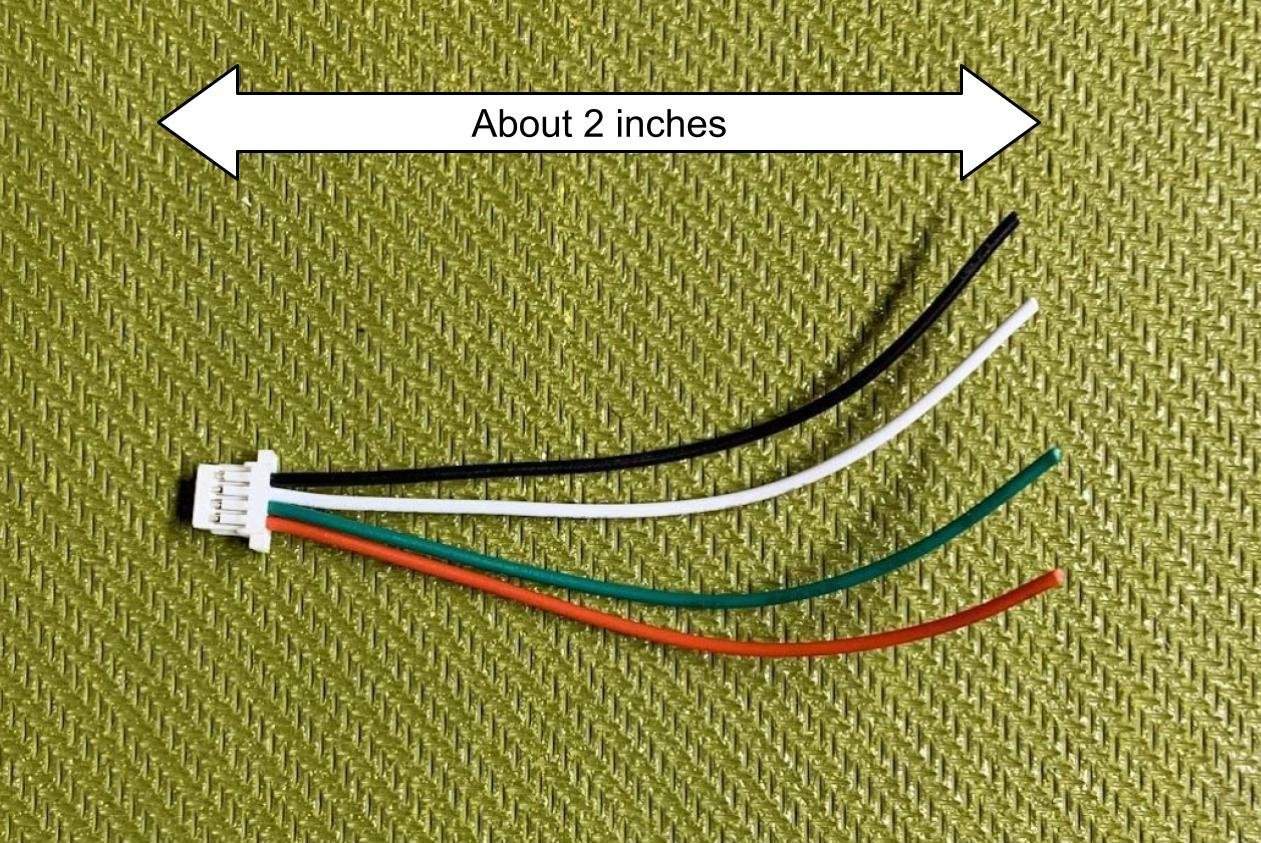
- Use the wires that have a white JST connector on one side (the one with 4 wires attached).
Note: In your kit, the set of wires may have a yellow wire instead of the green wire in the following pictures. Use the yellow wire instead of the green wire in this case.
Cut wires to about 2 inches in length from the JST header.
Strip all 4 wires (22 gauge) so that about 1/8 inch of wire is exposed.
Twist strands of each exposed wire to make it easier to insert to holes.

Solder the black (GND) wire to the GND pin on the microcontroller.
Solder the red (VCC) wire to the 3V3 pin on the microcontroller.
Solder the white wire (GPS TX) to Pin 7 (microcontroller RX).
Solder the green or yellow wire (GPS RX) to Pin 6 (microcontroller TX).
At this point, 4 wires should be soldered to the microcontroller:
- GPS GND to microcontroller GND
- GPS 3V3 to microcontroller 3V3
- GPS TX (white) to microcontroller RX (Pin 7)
- GPS RX (green or yellow) to microcontroller TX (Pin 6)
Important: If the TX (Pin 6) and RX (Pin 7) pins are soldered backwards (TX->TX and RX->RX, which is incorrect), the GPS will not communicate correctly with the microcontroller.

GPS Pinout Diagram
To fit the module into the case, these GPS wires need to be soldered to the back of the microcontroller. Inserting the wires through the holes from the back makes it easier to solder and also makes a stronger connection.
Insert the wires through the holes from the back of the microcontroller. Solder the exposed tips of the wires on the top of the microcontroller, as shown. The video on this page might be useful showing this.

Solder from the back, through the holes, to the top of the microcontroller

All GPS soldering complete!
Step 3: Solder Battery Wires
Important: Some included battery wires have 2 connectors on them: a JST connector and a Molex connector. The correct side is the JST connector. You can test which one is the correct one by inserting the battery into it.
Important: If the battery wires you received do not have both connectors on it, do not cut it in this step and skip to step 2.
- Cut the wires close to the Molex (the incorrect) header, so that the JST (the correct) header has the whole length of both wires attached to it.

Cut the red (power) wire in half, so that half of the wire is still connected to the JST connector. Don't cut the ground (black) side.
Strip both wires so that about 1/8 inch of wire is exposed.
Using the red power wire that you just cut from the battery connector wires, strip both sides, so that about 1/8 inch of wire is exposed.
Tip: Tin the tips of the exposed wires
Solder one of the red wires to the middle pin of the switch.
Solder the other red wire to one of the edge pins of the switch.


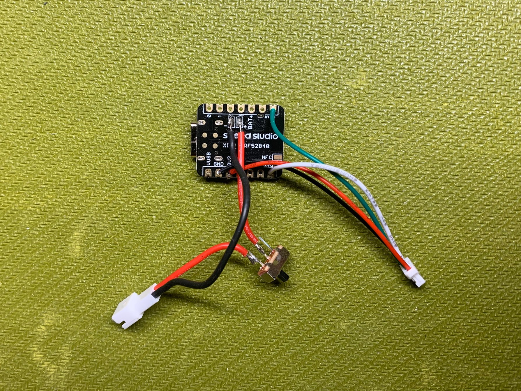
- On the back of the microcontroller, there are 2 exposed pads that are labeled “BAT+” and “-”. Tin these pads on the microcontroller.

Solder the black (ground) battery connector wire to the exposed pad that is labeled “-”. For reference, it is the one closest to the USB-C port.
Solder the red (power) wire (the other end of which should be connected to the switch) to the pad labeled “BAT+”.
Note: It can be helpful for fitting the module into the case to orient the wires with the wires directed inward (see picture)
- Soldering is complete!
Assembly Instructions:
Important: Install the GPS first. The GPS module will be difficult to install if the microcontroller is installed first.
- Slide the GPS module in at a low angle. Make sure the ceramic antenna is oriented against the top of the case (the label of the GPS module should be visible when installing).
Note: There will be some play (moving) when the GPS module is placed correctly. This was a design decision to facilitate inserting the module into the case.
- Insert the microcontroller so that the USB port fits into the slot.
Important: Make sure the wires do not get caught underneath the microcontroller as you insert the microcontroller.
Push until you hear a click. The click means the clips on the case have engaged.
Remove the adhesive cover from the foam piece and attach it to one side of the battery.
Place the battery in the case, with the foam oriented so that one side of the foam is stuck to the battery and the other side of the foam is against with the GPS module. The purpose of this foam is to protect the battery from the rest of the components in the module.
Push the switch into the switch slot. Note that this may require some force, but be careful not to push too hard, or you might break the ridges on the case that hold the switch in place.
Place the top part of the case onto the bottom case.
Assembly is finished!
Installation Instructions
For more information on installation and where to put the module so it is compliant, see the User Manual.
Attach one side of the provided Velcro strip to the bottom of the module. Important: The top of the module is the side with a hole for the LED. Place the Velcro on the opposite side.
Attach the other side of the provided Velcro to your aircraft. Make sure it is in a place where the module can get good GPS signals and can effectively broadcast Remote ID messages. For more information on where to place it, see the User Manual.